
Preserve Design Intent
Understand the critical function and interfaces before proposing changes to geometry, tolerances or material.
Bring manufacturing knowledge into your design before production begins. Our design for manufacturability review connects part function with material selection, tool access, workholding, tolerances, finishing and inspection.
From the first concept to repeat orders, identify manufacturing risks, agree practical improvements and verify the approved design through prototype and pilot feedback.
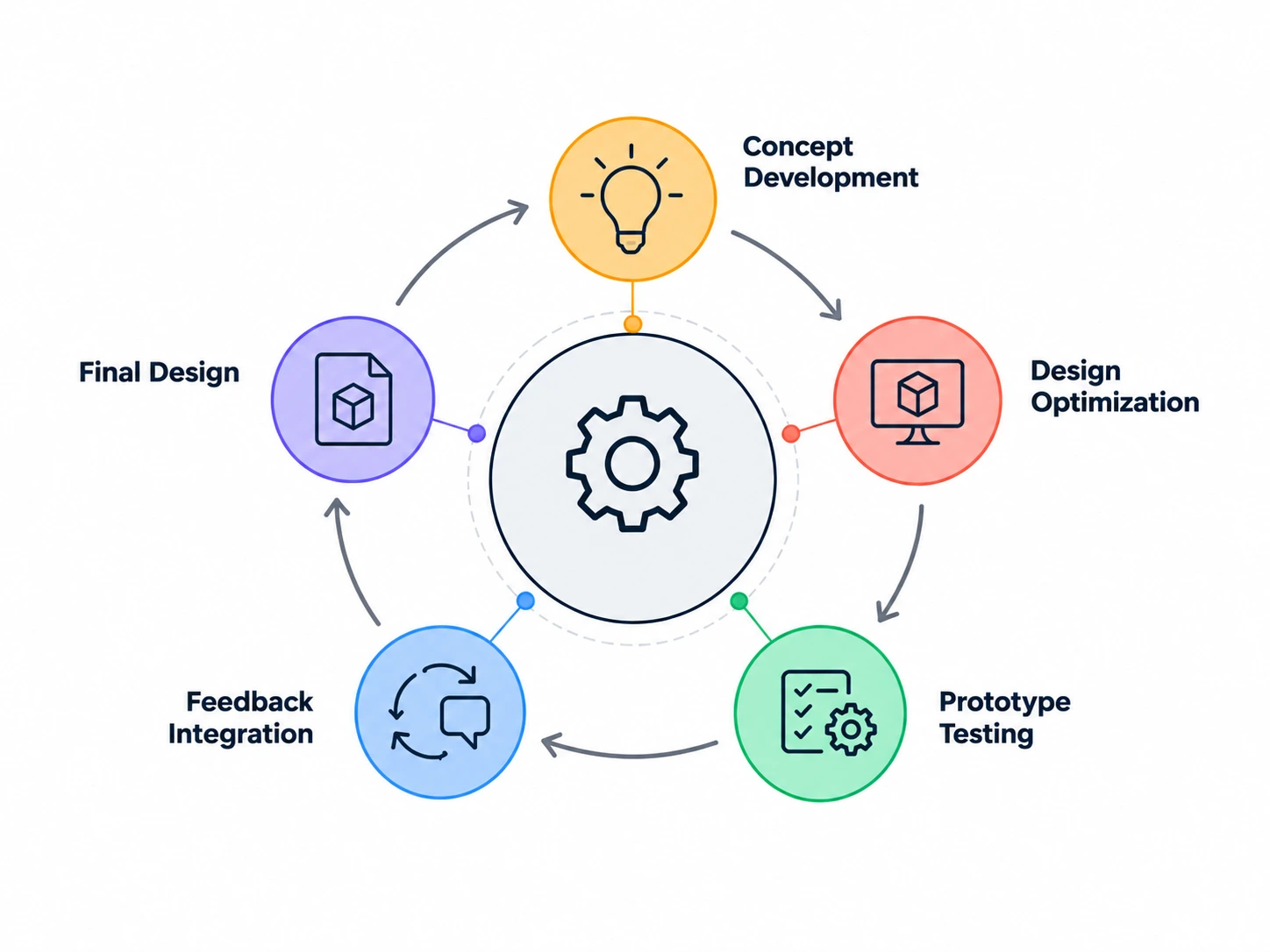
Design for manufacturability, or DFM, considers how a product will be made while the design is being developed. It connects manufacturing feasibility, efficiency, cost and quality so the intended component can be produced consistently.
For CNC machined parts, that means reviewing the drawing and model against real cutting tools, fixtures, material behavior, finishing processes and measurement methods. The objective is to preserve the part’s function while removing avoidable manufacturing difficulty.
DFM is a continuing engineering activity. Early review informs the design; prototype and pilot results test those decisions; production feedback and engineering changes keep the review current. The customer retains design authority, and proposed changes require approval before implementation.
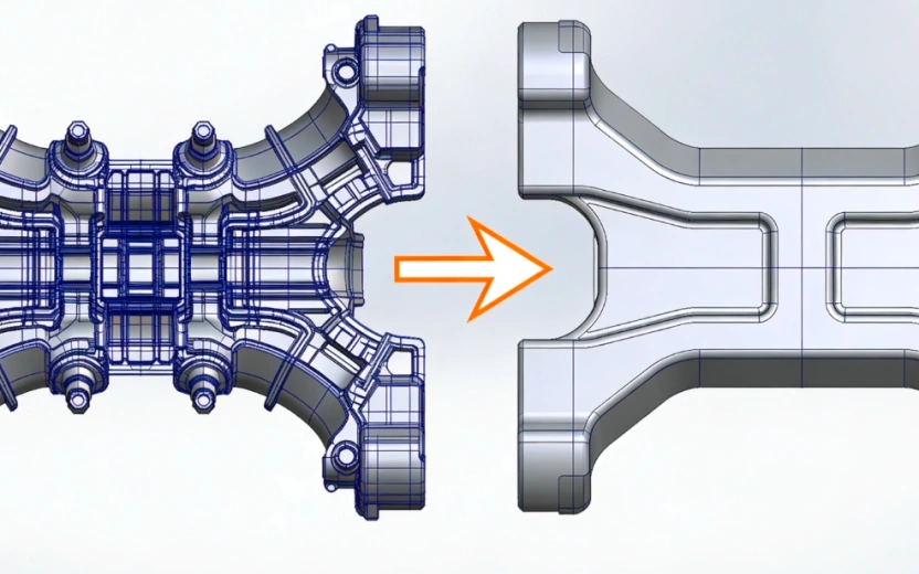
Understand the critical function and interfaces before proposing changes to geometry, tolerances or material.
Review the design with the equipment, tools, workholding and production conditions needed to make it.
Connect each agreed action to an approved revision, a verification method and a recorded release decision.
Reviewing manufacturability early helps prevent issues that otherwise emerge during machining, assembly or acceptance. Cost, quality and delivery improve through specific design and process decisions, with the effect verified for the component.
Connect the design to a viable machining process before release. Review feature access, setup requirements and equipment needs while geometry is still open to change.
Reduce unnecessary operations, special tooling, excess stock removal and inspection effort. Compare alternatives against the component’s actual function and production quantity.
Use clear datums, functional tolerances and stable workholding to reduce variation. Address deformation, burrs and assembly risks before they become repeat production issues.
Resolve manufacturing questions before a prototype or pilot build. Use build feedback to close specific design and process actions rather than repeating the same problems.
Make critical features accessible to inspection and connect each requirement to a suitable measurement method. Plan verification with the design and process route.
Review material availability, standard tooling and outside-process requirements early. Avoid unnecessary dependence on a unique route when a practical alternative meets the requirement.
DFM starts while the design can still change efficiently and continues through validation and repeat production. Each stage has a different question to resolve.
Compare materials, stock forms and potential manufacturing routes. Identify complex or nonstandard features before the concept becomes a fixed production design.
Review geometry, tolerances, interfaces, assembly access and inspection access as the model and drawing develop. Separate functional requirements from features that can be simplified.
Bring design, manufacturing, quality and sourcing perspectives together before design freeze. Record manufacturing risks, proposed changes, decision owners and the conditions for release.
Use the first build to examine machining difficulty, distortion, burrs, fit and measurement access. Record observations against the exact revision and turn them into specific actions.
Review cycle time, first-pass yield, defect patterns, tooling and inspection performance under representative conditions. Agree pilot quantities and acceptance evidence for the program.
Use recurring production feedback for continuous improvement. Reassess changes to geometry, material, tooling, processes or inspection before implementing the approved revision.
Our CNC part review covers design inputs, feature geometry, process planning and quality verification. Manufacturing concerns and proposed actions are assessed against the drawing, component function and production requirements.
Do the 2D drawing and 3D model describe the same controlled configuration?
Which features control fit, motion, sealing, load transfer or another critical function?
Is the specified grade, condition and starting stock suitable for the part and production route?
Can the cutting tool reach each feature without interfering with surrounding geometry?
Can the part remain stable during cutting, clamping and release from the fixture?
Are hole depths, thread engagement and edge conditions defined and accessible?
Can the component be located and clamped without damaging functional surfaces?
Is the proposed process practical for both the first build and repeat orders?
Can mating parts be assembled in the intended sequence with adequate access?
Are tolerance relationships functional, unambiguous and measurable?
Are the treated surfaces, roughness, masking and final dimensions clearly specified?
What evidence is needed to close the review and release the approved configuration?
Design, manufacturing, quality and sourcing perspectives are brought together in a structured review. Each finding moves from a documented concern to an agreed action and a verified outcome.
Confirm the component’s purpose, drawing revision, material, quantity and acceptance requirements. Identify the customer decision owners and the manufacturing, quality and sourcing input needed.
Review equipment access, workholding, tooling, machining sequence, finishing and measurement capability against the proposed geometry. Compare practical manufacturing routes.
Examine design inputs, feature geometry, process planning and quality verification systematically. Record the requirement, manufacturing concern and proposed action for each finding.
Discuss findings with the design owner. Assign risk priorities, responsibilities, target dates and closure evidence. Record accepted recommendations and any requirements that must remain unchanged.
Use prototype measurements, assembly feedback and pilot-run data to check the agreed actions. Close findings against evidence and release only the approved drawing and process configuration.
The report connects the reviewed design to manufacturing findings, customer decisions and closure evidence. Agree the format and depth of the review with the project scope.
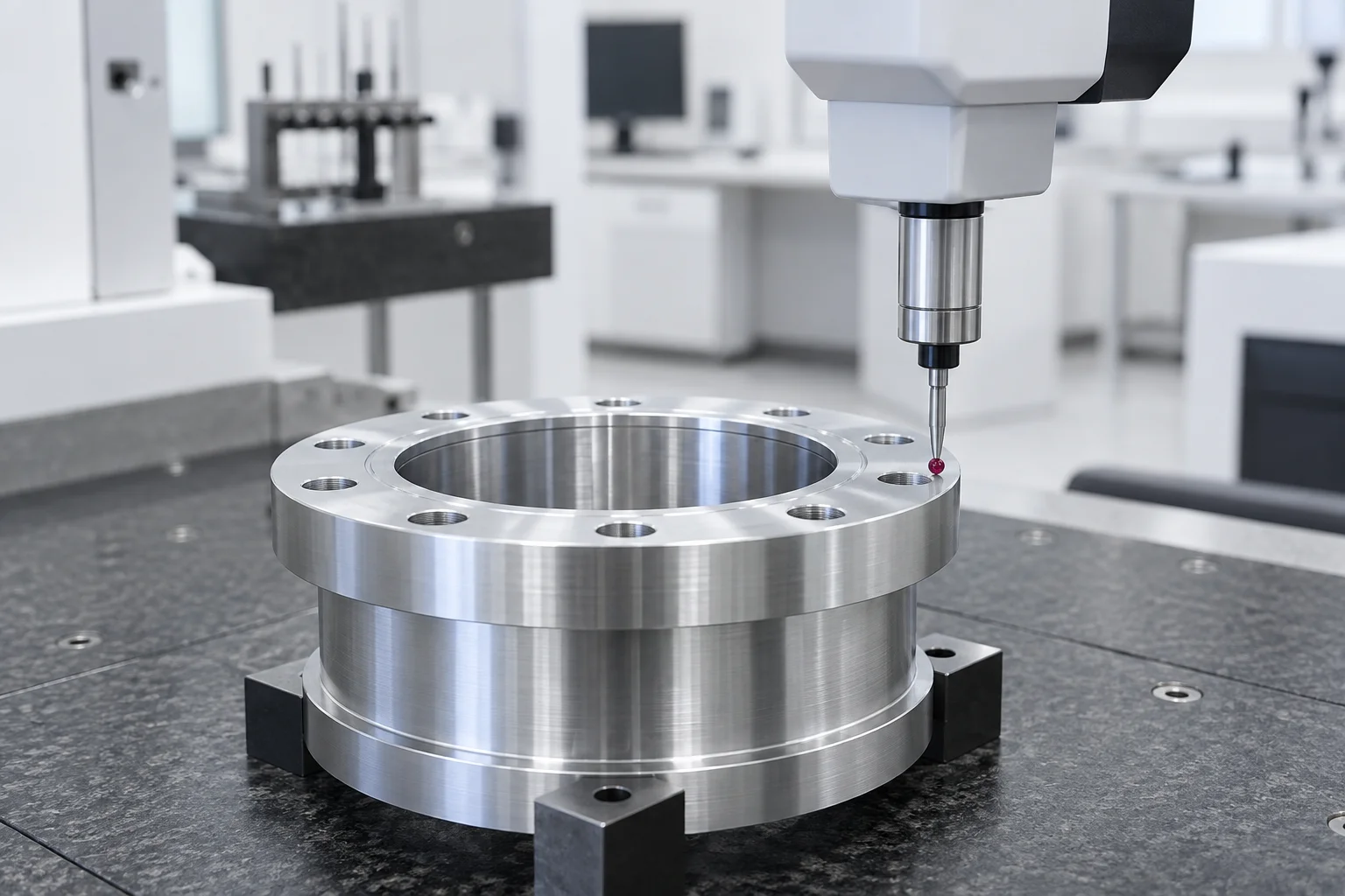
The review method stays consistent while component function, application risk and customer acceptance requirements determine what needs closer attention.
Review sealing geometry, vacuum-facing surfaces, material condition, cleaning access and the influence of coatings on critical fits. Align surface and cleanliness acceptance with the customer’s equipment requirements.
Explore Semiconductor Equipment MachiningReview drawing-defined critical characteristics, datum relationships, material traceability and first-article measurement access. Coordinate proposed changes with the customer’s configuration and approval requirements.
Explore Aerospace MachiningReview bearing seats, runout-related interfaces, mating fits, clamp access and repeat-build consistency. Use the assembly’s motion and load requirements to decide which feature relationships are critical.
Explore Robotics MachiningReview edges, burr access, material traceability, cleaning requirements and small-feature inspection. Plan component evidence to support the customer’s validation requirements without replacing product-level approval.
Explore Medical Devices MachiningApproved design decisions feed the next manufacturing stage. Keep the review connected to prototype learning, production evidence and the final material and finish specification.
Start during concept or detailed design, before geometry and manufacturing cost are fixed. Repeat the review before release, after prototype learning, during pilot validation and when an engineering change affects the manufacturing route.
Prepare the latest STEP model and dimensioned drawing, material and surface-finish requirements, prototype and forecast quantities, target dates, critical features and required inspection records. Include mating-part or assembly information where it explains the part’s function.
No. The review identifies manufacturing concerns and proposes actions. The customer retains design authority, and changes to geometry, material, tolerances or specifications require approval before implementation.
No. Critical tolerances remain tied to function and acceptance requirements. DFM identifies unnecessary constraints on noncritical features and checks whether the specified relationships can be manufactured and measured consistently.
No. The selections on this page help describe the topics you want reviewed. A component-specific DFM review needs the drawing, model, application requirements and engineering evaluation.
DFM helps resolve design and manufacturing risks before and during NPI builds. Prototype and pilot evidence closes the agreed actions. Where the customer requests PPAP, the approved configuration and production controls contribute to the required product and process evidence.