CNC Machining Services For Robotics

Robots are only as precise as the parts they are built from. We machine structural links, joint housings, end effectors and motion components where mass, stiffness, fit and iteration speed all shape the final system performance.

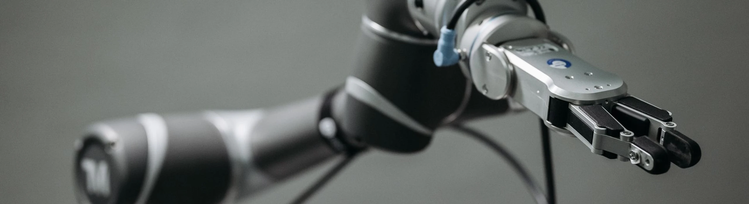
Robot wrist and two-finger gripper extending from an articulated robot arm

CNC Machining For The Robotics Industry

Robotics combines aerospace-like precision, rapid product iteration and volumes that can move from one-off research builds to deployed production platforms. Every arm link, bearing bore, housing and shaft contributes to the robot assembly stack-up.

We support robotics teams with structural arm links, joint housings, gripper components, gearbox housings, shafts, pulleys, couplings, sensor mounts, base plates and development parts. Prototype revisions and repeat production are reviewed through the same engineering-led manufacturing process.

Drawing revision, datum structure, critical fits, assembly interfaces, target cycle and expected production ramp should be shared with the RFQ so the quotation reflects both prototype speed and production discipline.

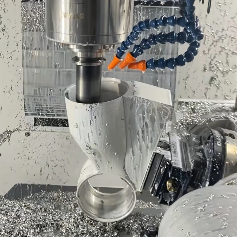
CNC spindle machining a hollow metal housing with intersecting bores inside a machine enclosure

Types Of Robotics Parts We Manufacture

Robotics components are planned around stiffness, mass, fit, motion accuracy and repeatable assembly. Each part family is reviewed against the features that influence the complete robotic system.

The Challenges Of Robotics Parts Machining

Robotics parts often look simple, but their functional requirements sit in the relationships between features: bore alignment, stiffness, mass, fit and revision control.

The manufacturing route is planned around how the part behaves after unclamping and how it performs inside the larger motion system.

Lightweighting Without Losing Stiffness

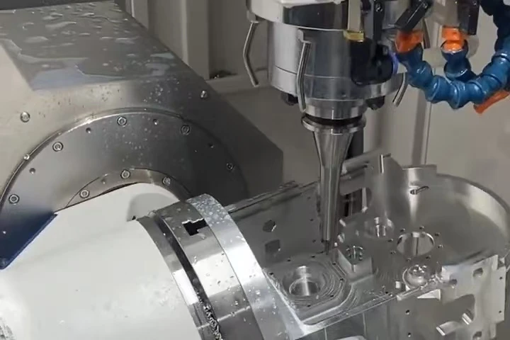
Thin walls, pocketed webs and optimized ribs are machined with distortion-control strategies so weight reduction does not become a loss of geometry.

Thin-Wall Stability
Balanced roughing, supportive fixturing and verification after unclamping help keep pocketed robotics structures true to the released drawing.
Manufacturing Processes For Robotics Components

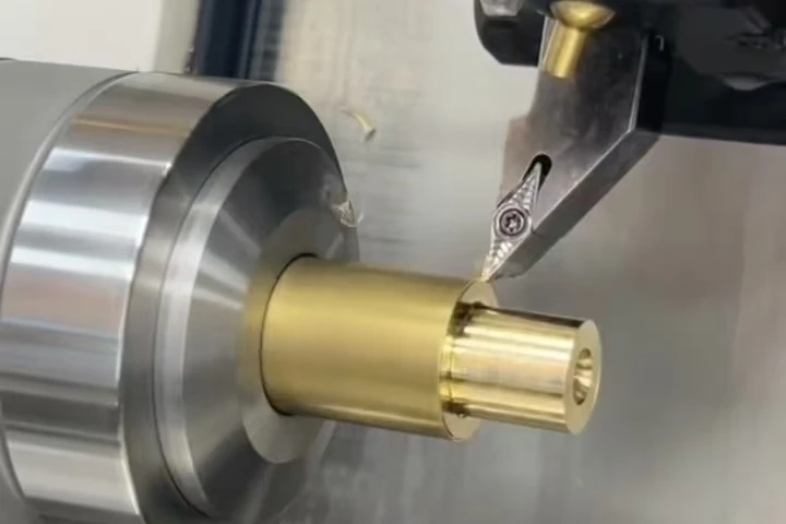
Our robotics manufacturing processes include CNC milling, CNC turning, mill-turn machining and Swiss machining. The route follows the drawing, material, functional datums and production stage.

CNC Milling

Use 3-axis and 5-axis milling for links, housings, base plates and structural members. Bearing bores, dowel holes and multi-face features are machined around datum continuity, wall stability and measurement access.

  • Arm Links
  • Joint Housings
  • Bearing Seats
  • Multi-Face Datums
CNC milling spindle cutting a metal workpiece on a rotary fixture

How Our Robotics CNC Machining Service Process Works

The process covers drawing review, material confirmation, machining route planning, first article inspection, production machining, finishing and delivery records tied to the current drawing revision.

Engineering Review

  1. 01

    Drawing Submission

    Provide the STEP model and dimensioned drawing with the current revision, material grade, quantity, surface finish, required delivery date and inspection requirements. Where required, an NDA is signed before drawings and models are exchanged.

  2. 02

    DFM Review

    Review geometry, dimensional and geometric tolerances, stock condition, tool access, workholding and measurement access. Identify features that affect machining feasibility, dimensional stability or inspection, and resolve proposed drawing changes with your engineering team.

  3. 03

    Technical Requirements Review

    Confirm the drawing revision, material specification, datum scheme, critical dimensions, surface finish and inspection requirements. Resolve drawing queries and document approved changes. Prepare the quotation from the confirmed part requirements, quantity and delivery schedule.

Production Preparation

  1. 04

    Robotics CNC Machining Process Planning

    Define the operation sequence, machining datums, fixtures, cutting tools and cutting parameters. Prepare the NC program and inspection plan, review toolpaths through machine simulation, and establish the setup instructions for the first-article machining trial.

  2. 05

    Material Procurement

    Specified material grades and stock forms are purchased exclusively from approved or qualified suppliers, matched to the requirements of your drawing and purchase order.

  3. 06

    Incoming Material Inspection

    Check stock identification, dimensions, surface condition and material certificates against the specified grade, condition and purchase order. Record the heat or batch number and link the accepted material to the production work order.

Controlled Machining

  1. 07

    First Article Inspection

    Machine the first article using the planned NC program, fixtures and tools. Inspect drawing characteristics with the specified measurement methods, record the results and correct setup or program deviations before batch production begins.

  2. 08

    Production Machining

    Run the approved Robotics CNC machining program with the documented fixture setup, tooling and cutting parameters. Maintain the specified datums and machining sequence, and record approved changes to programs, tool offsets or setup instructions.

  3. 09

    In-Process Inspection

    Measure critical dimensions and geometric characteristics at the intervals defined in the inspection plan. Monitor tool wear and dimensional trends, adjust offsets where appropriate, and recheck affected features after adjustment.

Verified Delivery

  1. 10

    Machined Part Inspection

    Check the completed machining operations against the drawing and review the in-process inspection results. Record dimensional conformity and segregate nonconforming parts before the batch proceeds to finishing or other subsequent operations.

  2. 11

    Post-Machining Operations

    Complete the specified deburring, grinding, polishing, surface treatment or heat treatment. Check treatment records and reinspect features affected by material removal, coating thickness or heat-treatment distortion.

  3. 12

    Final Inspection And Shipment

    Inspect finished parts against the drawing and final inspection plan, including dimensions, surface condition and finish requirements. Compile the required material certificates and inspection reports, verify quantity and identification, then pack parts to prevent damage during shipment.

Materials For Robotics Components

Material choice affects stiffness, mass, wear behavior, corrosion resistance and cost. Grade and stock form are confirmed before procurement, with no substitution without written approval.

Showing 7 Materials: Metals.

Aluminum 6061-T6

A practical default for robotics: light, machinable and anodize-ready for links, brackets and housings.

Typical Applications

Arm links, brackets, housings and development components

Aluminum 7075-T6

Higher strength supports compact, loaded structures where 6061 would drive a heavier design.

Typical Applications

Highly loaded joint parts and compact structural components

Aluminum 5083

Strong weldability and good strength retention suit larger fabricated structures and base components.

Typical Applications

Frames, bases and welded structural assemblies

MIC-6 Cast Aluminum Plate

Stress-relieved cast plate offers flatness stability for large plates where rolled stock movement is a risk.

Typical Applications

Base plates, fixture plates and frames

Stainless Steel

  • 304
  • 316
  • 17-4 PH

Corrosion-resistant and high-strength options for washdown, food-adjacent, marine or loaded motion components.

Typical Applications

Shafts, pins, wear components and corrosion-resistant hardware

Alloy Steel

  • 4140 pre-hardened
  • 8620
  • 12L14

Shaft, gear and economical production options selected around strength, wear and volume cost.

Typical Applications

Drivetrain components, shafts, gears, spacers and non-critical volume parts

Brass C360

Highly machinable metal for bushings, wear components and conductive hardware.

Typical Applications

Bushings, conductive components and economical precision parts

Surface Finishes For Robotics Components

Finishes are selected for corrosion protection, wear resistance, identification, appearance and assembly control. Thickness, masking and post-process inspection are quoted to the drawing.

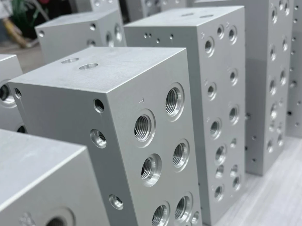
Natural-colored anodized metal blocks with threaded bores and side holes

Anodizing (Type II)

Natural or custom color; thickness and masking per drawing

Type II anodizing provides corrosion protection for aluminum. Clear natural or custom dyed colors support appearance and axis identification; specify a color reference and acceptance sample.

Typical Applications

Links, brackets, housings, covers and axis-coded hardware

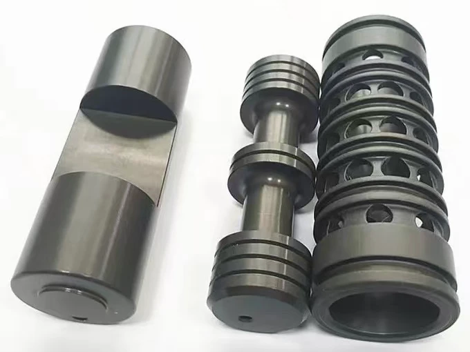
Dark hard-anodized cylindrical parts with grooves, shoulders and machined flats

Hard Anodizing (Type III)

Type III for wear resistance

A denser oxide layer supports sliding surfaces and repeated contact areas.

Typical Applications

Gripper fingers, guides and wear-contact aluminum parts

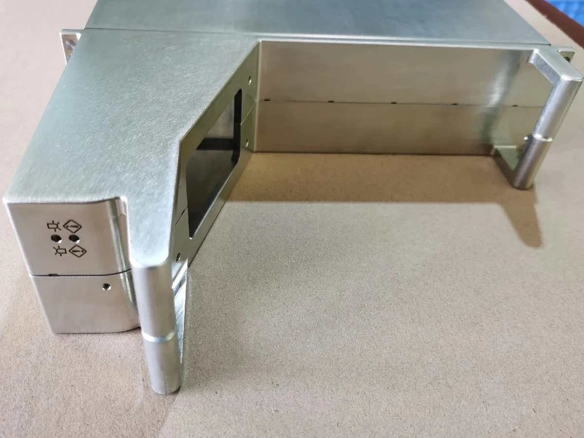
Zinc-finished metal enclosure with machined openings and corner posts

Zinc Plating

Economical steel corrosion protection

A practical finish for indoor steel brackets, shafts and fasteners where coating thickness is acceptable.

Typical Applications

Steel brackets, hardware and indoor-service components

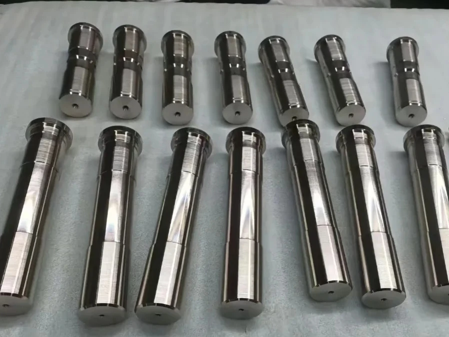
Nickel-finished metal shafts with stepped diameters arranged on a white sheet

Nickel Plating

Controlled thickness per drawing

Nickel plating provides durable corrosion protection and a uniform appearance on steel or selected aluminum parts.

Typical Applications

Exposed steel components and wear surfaces

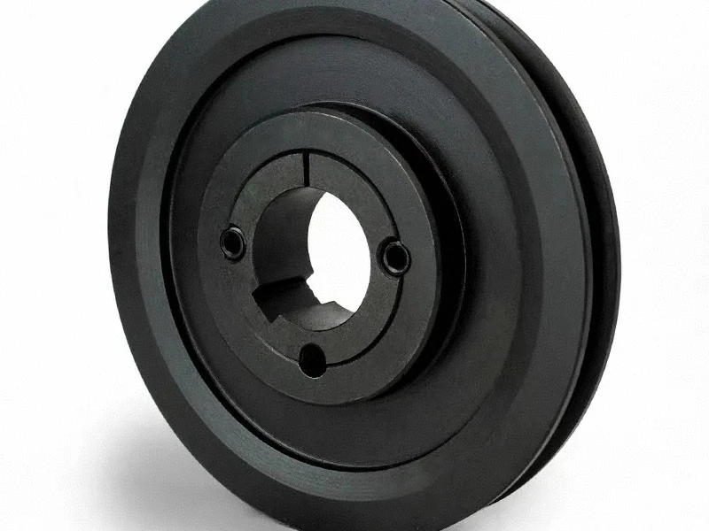
Black-finished circular metal component with a keyed bore and concentric steps

Black Oxide

Dimensionally light steel finish

Black oxide supports a dark appearance with minimal dimensional change on precision steel fits.

Typical Applications

Shafts, couplings and exposed steel hardware

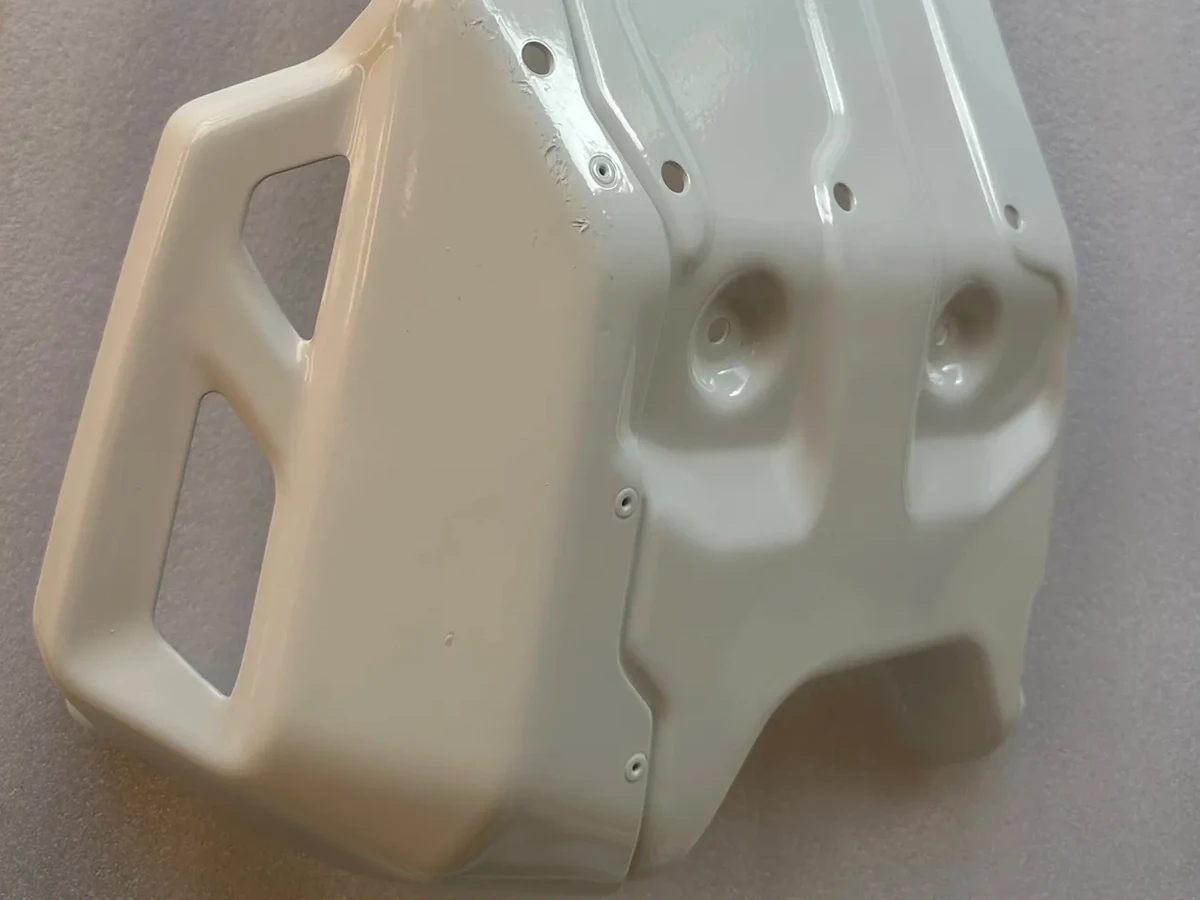
Off-white powder-coated metal housing with mounting holes and rectangular cutouts

Powder Coating

Durable color coating

Powder coating provides production-ready color and abrasion resistance on frames, covers and enclosures.

Typical Applications

Frames, covers and equipment panels

Machined metal ring with a two-dimensional code and alphanumeric laser marks on its outer surface

Laser Engraving

Permanent identification

Part numbers, logos, alignment marks and assembly references can be applied without labels or inks.

Typical Applications

Marked production parts and assembly references

Quality Assurance For Robotics Programs

Robotics QA focuses on the measurements that become motion performance: bore alignment, hole patterns, drivetrain relationships, revision control and assembly fits.

Documentation is scaled to the program stage, from development inspection records to production material certificates, FAI reports and certificates of conformance.

Why Choose Us For Your Robotics Program?

One team connects fast RFQ response, manufacturability feedback, machining, finishing, inspection and repeat production support for motion-critical robotics components.

Robot-Part Manufacturing Insight

Bore alignment, link stiffness, lightweighting and assembly fits are reviewed as functional requirements, not just drawing notes.

Fast Iteration Support

Complete RFQs receive an initial engineering response within one working day. Retained drawing revisions and process records support subsequent prototype iterations.

Prototype-To-Production Continuity

Development, pilot and recurring production can run through the same quality standard and supplier route.

Thin-Wall And Lightweight Capability

Pocketed and ribbed structures are machined with distortion control and verified after unclamping.

Machining Through Finished Assembly

Machining, finishing, heat treatment, marking, inserts and fit checks can be coordinated under one PO.

Practical Engineering Feedback

Tolerance, wall thickness, material and finishing risks are raised during quotation with alternatives where appropriate.

Frequently Asked Questions

Practical answers about robot part scope, joint accuracy, iteration speed, materials, assembly support and documentation.

What Robotics Parts Do You Machine Most Often?

Arm links, joint housings, end effectors, gripper parts, gearbox housings, shafts, couplings, sensor mounts and base plates from prototypes through production volumes.

Can You Hold The Bore Alignment Robot Joints Require?

Yes, subject to drawing review. Bearing bores are routed for single-setup machining wherever geometry allows, with alignment and perpendicularity verified to the drawing.

How Fast Can Prototype Iterations Move?

Complete RFQs receive an initial engineering response within one working day; quotations follow confirmation of scope. Prototype lead time depends on geometry, material, finish and inspection scope, and revision changes can build from retained program context.

Can You Support R&D Builds And Production Volumes?

Yes. Development prototypes, pilot builds and recurring production can follow one controlled manufacturing and inspection approach.

What Material Is Best For Robot Arm Links?

6061-T6 is common; 7075-T6 is reviewed where strength allows a lighter design; MIC-6 is useful for stable base and fixture plates. Final selection should follow load and assembly requirements.

Do You Offer Bearing Pressing Or Insert Installation?

Yes, assembly support such as bearing pressing, insert installation and fit checks can be included when specified with the RFQ.

What Documentation Do You Provide?

Material certificates, FAI reports, dimensional inspection records and certificates of conformance can be supplied when agreed at quotation.

Can We Put An NDA In Place Before Sending Drawings?

Yes. An NDA can be completed before drawing exchange.