CNC Turning Services

We manufacture precision cylindrical components from prototype through repeat production. MAZAK and TSUGAMI turning capacity combines OD and ID turning, facing, grooving, threading and selected live-tool features, supported by DFM review, planned inspection and traceable documentation for aerospace, semiconductor, robotics and medical applications.

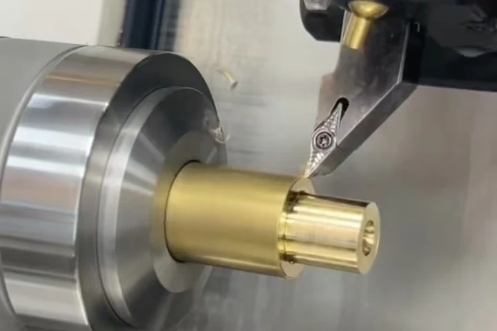
CNC turning of a precision rotational metal component

CNC Turning Capacities

Our CNC turning services combine MAZAK and TSUGAMI platforms with chucked and bar-fed machining to produce shafts, bushings, sleeves and threaded fittings. OD and ID turning, grooving and threading establish concentric features from a common datum, while selected live-tool operations add cross-holes and flats without a separate milling setup. The result is fewer transfers, consistent assembly fits and efficient repeat production.

From development parts to production batches, DFM review, material traceability and drawing-based inspection support each order. Complete RFQs receive an engineering response within one working day; the quotation follows confirmation of the manufacturing scope.

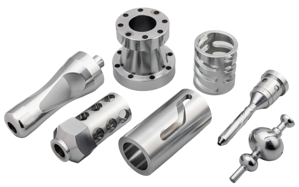
Assorted turned metal parts with flanges, bores, slots, cross-holes and stepped profiles

The CNC Turning Machines We Run

Our turning resources combine MAZAK and TSUGAMI platforms with chucked, bar-fed, live-tool and back-working routes. Machine selection is based on part diameter and length, stock form, material behavior, thread and groove complexity, feature relationships, inspection access and production volume.

MAZAK

Rigid turning platforms establish stable diameters, bores, faces, shoulders and threads from a controlled rotational datum, with selected driven-tool operations kept inside the same route.

  • Chucked And Bar-Fed Routes
  • OD And ID Turning
  • Grooving And Threading
  • Live-Tool Options

TSUGAMI

Precision turning capacity for smaller rotational components, detailed thread and groove requirements, front and rear operations and repeat batches produced from prepared stock or bar.

  • Small And Medium Diameters
  • Front And Back Operations
  • Driven-Tool Capability
  • Repeat-Batch Production

CNC Turning Capacity And Tolerances

The values below describe our confirmed CNC turning envelope. Dimensional values are specified in millimeters; inch equivalents are rounded. Final capability depends on material, stock condition, unsupported length, wall thickness, thread or groove geometry, feature relationships and measurement access. A tolerance tighter than the function requires can change tooling, cycle time, inspection method and scrap risk, so critical requirements are separated from general title-block tolerances during DFM review.

CapabilitySpecification
Linear Dimensions±0.13 mm (±0.005 in)
Hole Diameters±0.13 mm (±0.005 in)
Shaft Diameters±0.05 mm (±0.002 in)
ThreadsPer standard thread class and drawing requirements
Surface FinishAs-machined: Ra 125 µin (≈3.2 µm)
Maximum Part Size200 × 500 mm (7.9 × 19.7 in)
Minimum Part Size3 × 3 mm (0.12 × 0.12 in)
Minimum Feature SizeØ0.8 mm (Ø0.031 in)

How Our CNC Turning Service Process Works

The manufacturing sequence covers drawing and technical requirements review, process planning, incoming material inspection, first article inspection, production machining, surface treatment and final inspection. Machining instructions and inspection records are tied to the approved drawing revision and production batch.

Materials For CNC Turning

Turning performance depends on hardness, bar or blank condition, chip formation, heat response and the relationship between surface speed and tool life. We plan cutting tools, speeds, workholding, heat treatment allowance and inspection around the selected grade, with material certificates and specified lot traceability available for release.

ImageMaterial FamilyRegular GradesPerformance AdvantagesTypical Applications
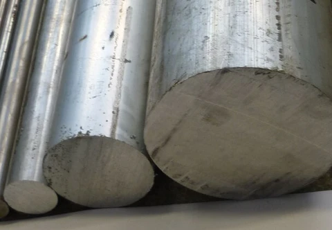
Round metal stock showing solid circular cut endsCarbon And Alloy Steel
  • 12L14
  • 1045
  • 4140
  • 8620
Good machinability or higher strength and fatigue resistance, with heat-treatment routes available for load-bearing and wear-critical features.Shafts, pins, custom fasteners, rollers and industrial components
Round metal stock showing solid circular cut endsStainless Steel
  • 303
  • 304
  • 316L
  • 17-4PH
  • 416
Corrosion resistance, strength and clean-service compatibility; free-machining and precipitation-hardening grades support different cost and performance targets.Vacuum hardware, medical equipment, aerospace fittings and fluid-control parts
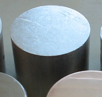
Short cylindrical metal blank with a bright sawn end faceAluminum
  • 6061-T6
  • 7075-T6
  • 2024-T3
Low density, fast cutting and strong thermal conductivity, with high-strength grades available for weight-sensitive structures.Robotics, aerospace, electronics and anodized turned parts
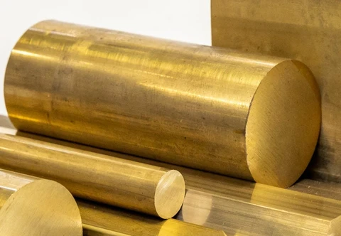
A solid brass cylinder with a circular cut face and visible machining linesBrass And Bronze
  • C360 brass
  • C17200 beryllium copper
  • bearing bronze
High machinability, conductivity or bearing performance, with selected alloys suited to sliding wear and spring-contact requirements.Fittings, bushings, electrical contacts and semiconductor components
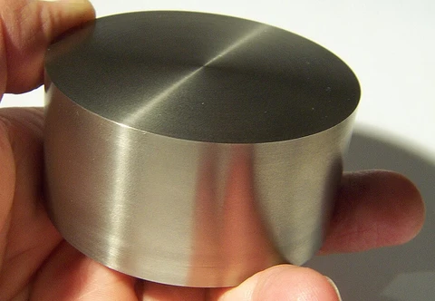
A short titanium cylinder held in a hand, with a flat circular end and straight sidesTitanium
  • Grade 2
  • Ti-6Al-4V (Grade 5)
  • Ti-6Al-4V ELI
High strength at low weight, corrosion resistance and biocompatible grade options, requiring controlled heat and tool-wear management.Aerospace, medical and corrosion-resistant turned components
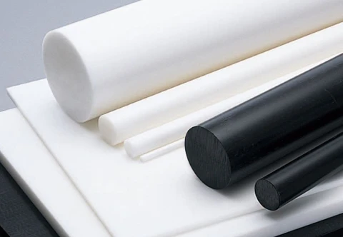
White and black polymer round stock with solid circular endsEngineering Plastics
  • POM (Acetal)
  • PEEK
  • Nylon
  • PTFE
Low mass, chemical resistance, electrical insulation and low-friction options, with workholding adapted to creep and thermal movement.Insulators, wear components, medical equipment and fluid systems

Surface Finishes

Finishes are selected around corrosion resistance, wear, sealing, electrical performance, cleanability and appearance. Allowance, masking and thread protection are defined before machining, and critical dimensions can be rechecked after finishing under the same order.

As-MachinedRa Per Machining Route And Drawing

A finish left directly by the cutting process, with controlled tool marks and no additional surface treatment. The process capacity table and drawing define the required roughness.

Typical Applications: Robotics journals and bearing seats

PolishingRa 0.2 µm

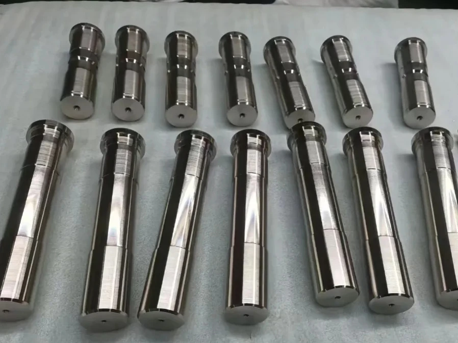
A mechanical finishing process that smooths the surface to reduce roughness and improve sealing, cleanability or appearance.

Typical Applications: Semiconductor sealing faces and vacuum bores

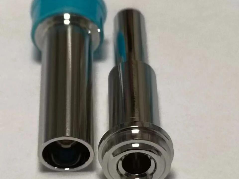
Two polished metal components with reflective cylindrical surfaces and hollow bores
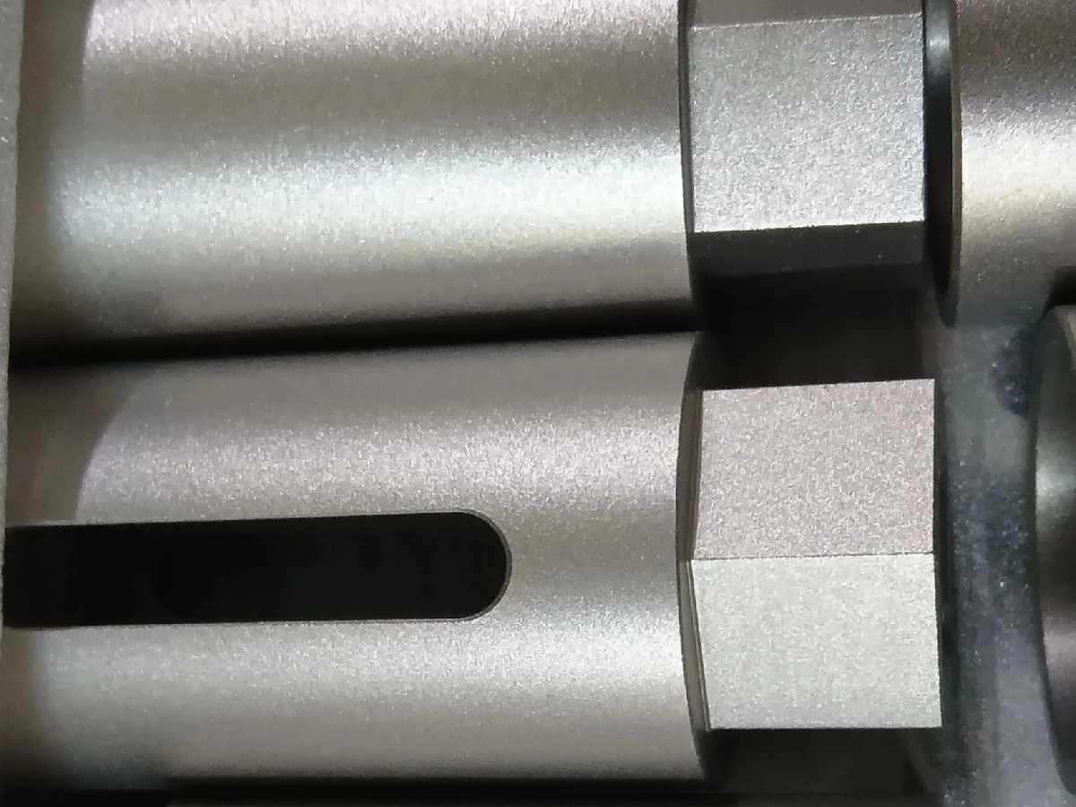
Bead BlastingUniform matte texture

A surface treatment that creates a uniform matte texture by blasting fine abrasive media onto the part surface.

Typical Applications: Aerospace and robotics surfaces

Matte-textured cylindrical metal components with flats and a longitudinal slot
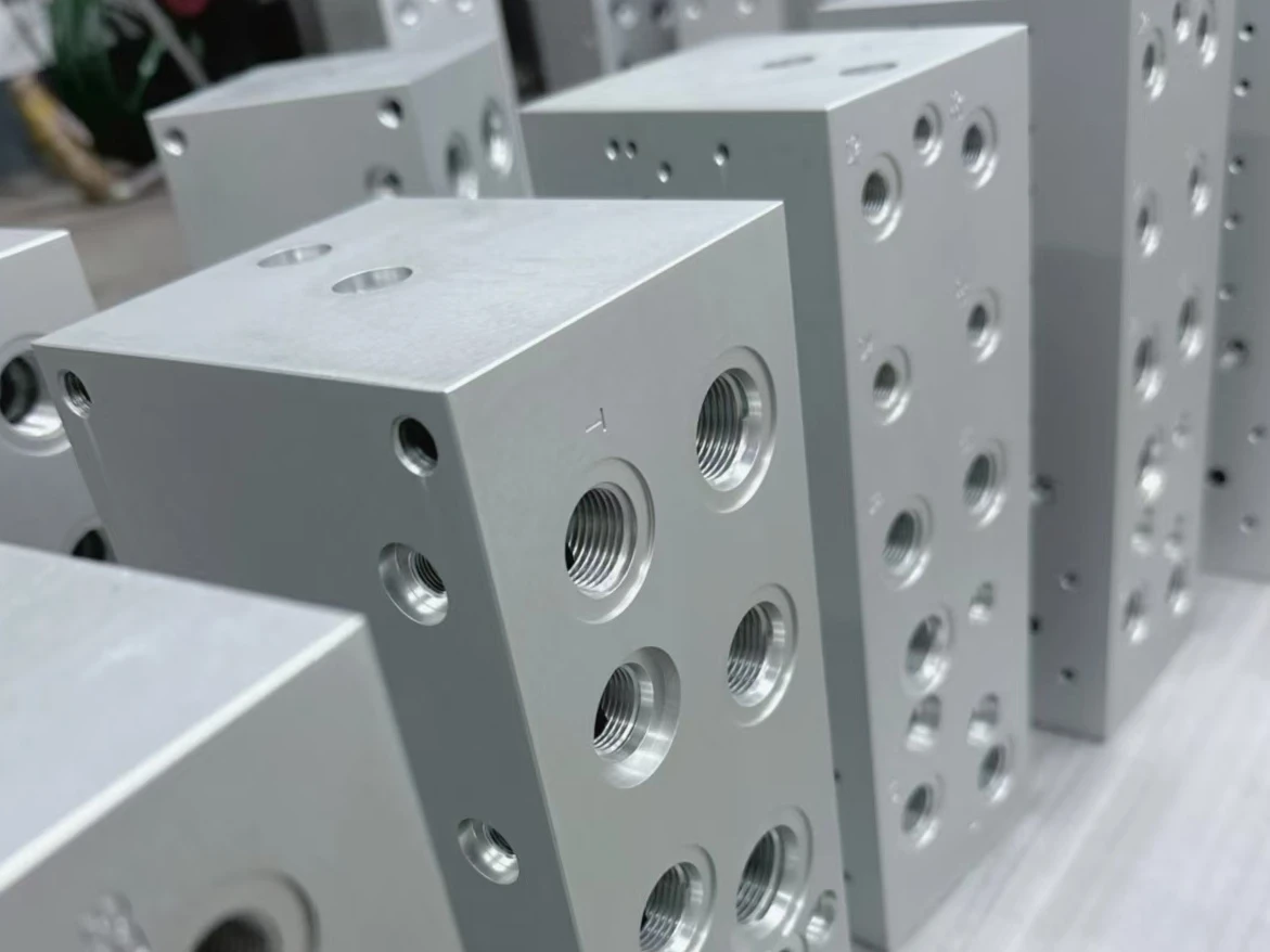
Anodizing (Type II)Natural or custom color; thickness, sealing and masking per drawing

Type II anodizing builds a protective oxide layer on aluminum for corrosion protection and appearance. Clear natural and dyed finishes are color options within the same process. A custom color reference and acceptance sample can be specified.

Typical Applications: Aluminum housings, robotics arms, brackets and visible components

Natural-colored anodized metal blocks with threaded bores and side holes
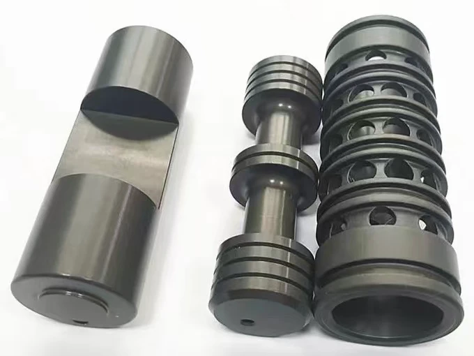
Hard Anodizing (Type III)Type III hardcoat; thickness, sealing and masking per drawing

Hard anodizing is selected for wear-resistant aluminum surfaces. Coating allowance and masking are planned around critical fits; any hardcoat color requirement is reviewed with the specified alloy and thickness.

Typical Applications: Sliding guides, bushings and wear-contact aluminum components

Dark hard-anodized cylindrical parts with grooves, shoulders and machined flats
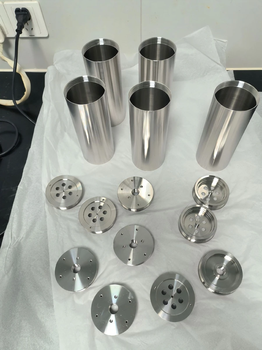
PassivationAMS 2700 / ASTM A967

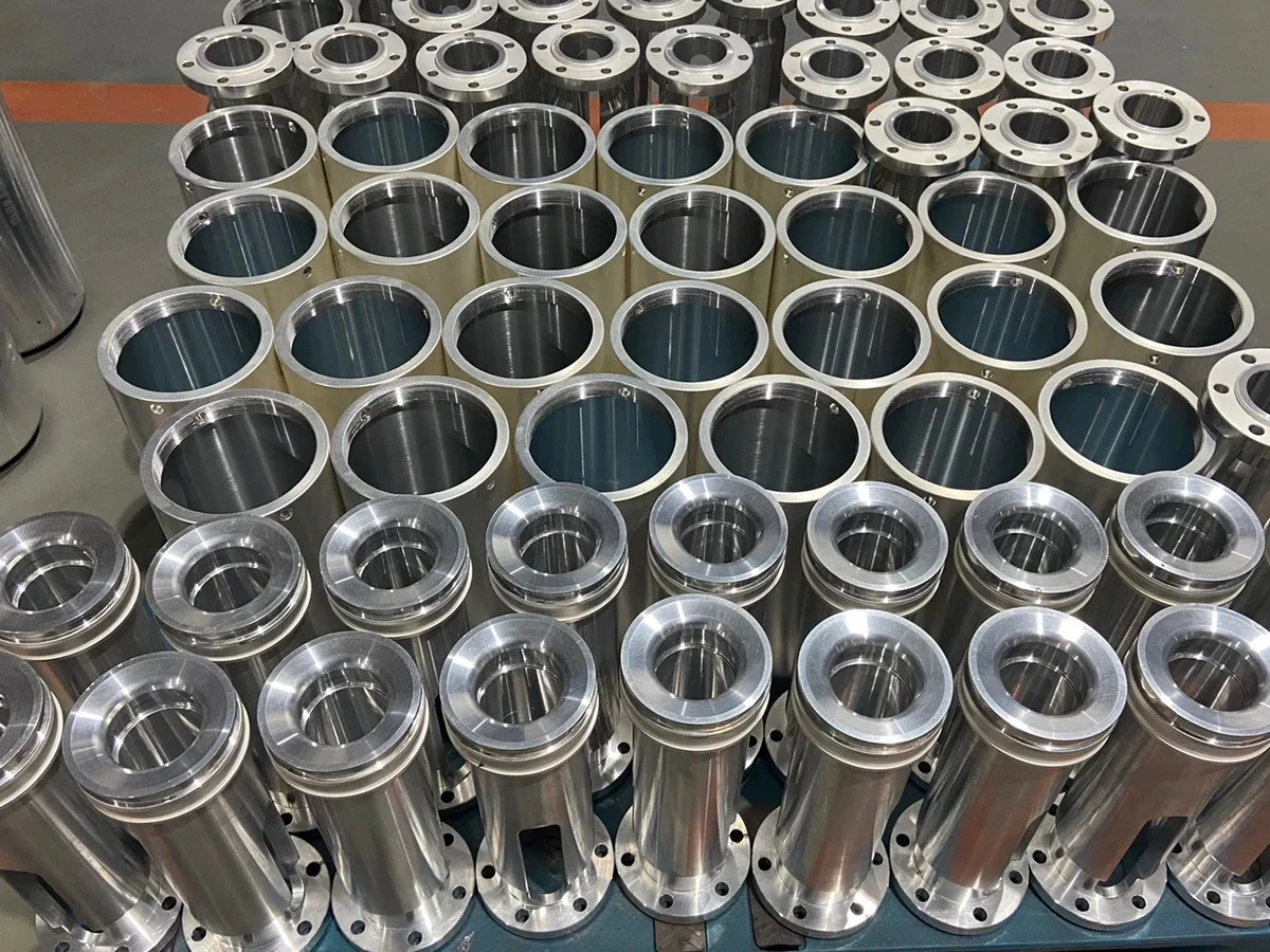
A chemical treatment for stainless steel that removes free iron from the surface and supports its natural corrosion resistance.

Typical Applications: 316L semiconductor and vacuum parts

Stainless cylindrical housings and circular end plates arranged on a white sheet
Electroless Nickel Plating5–50 µm, uniform on bores

A chemically deposited nickel coating that provides consistent thickness on complex geometry and improves corrosion and wear resistance.

Typical Applications: Semiconductor chambers and robotic leadscrews

Nickel-finished metal shafts with stepped diameters arranged on a white sheet
Gold PlatingPer semiconductor specification

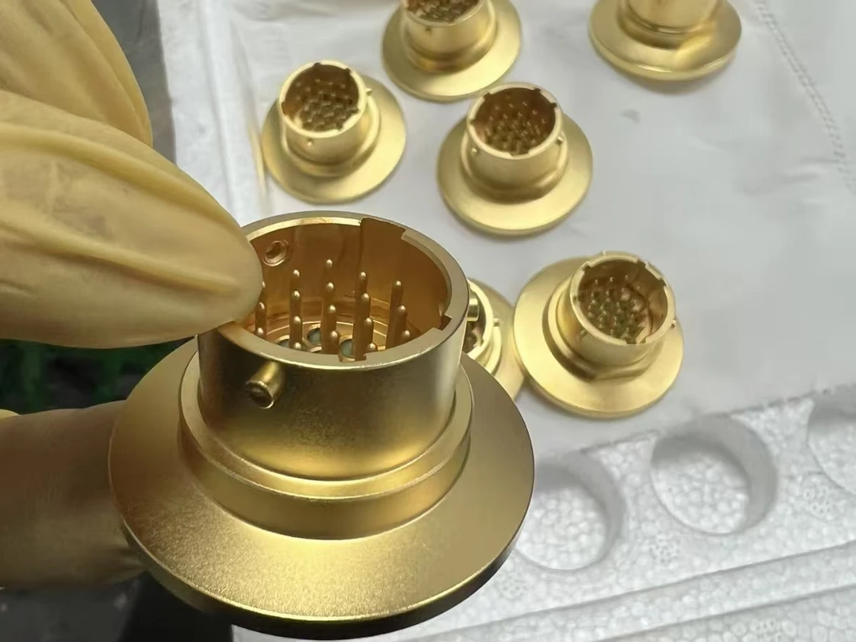
A corrosion-resistant precious-metal coating that provides stable electrical contact performance and low contact resistance.

Typical Applications: Precision contacts and semiconductor electrodes

Gold-colored connector housings with flanges and contact pins
Silver PlatingPer semiconductor specification

A highly conductive metallic coating used to improve electrical and thermal transfer on functional component surfaces.

Typical Applications: High-current contacts and conductive components

Silver-finished cylindrical components with bores and mounting flanges arranged in rows
Black OxideDrawing-specified military standard

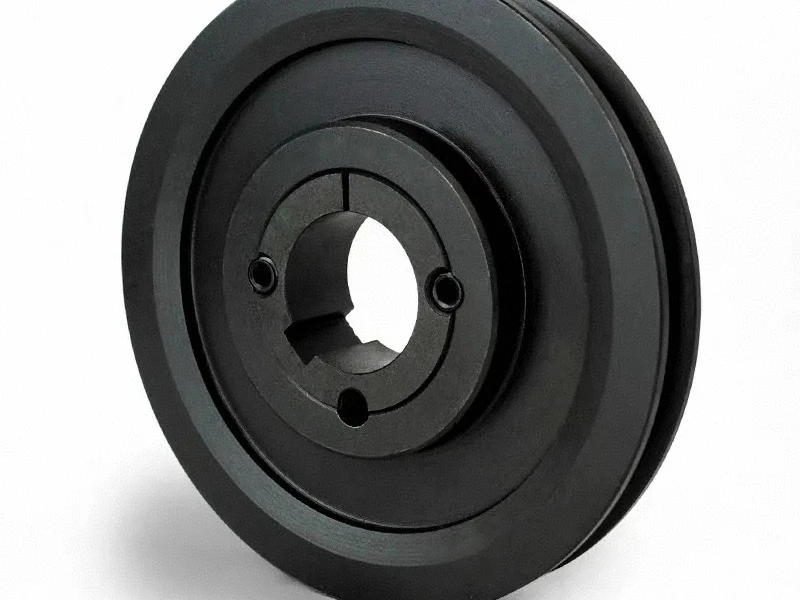
A thin conversion finish for ferrous metals that reduces glare and adds mild corrosion protection with the specified seal or oil.

Typical Applications: Steel fasteners, tooling and fixtures

Black-finished circular metal component with a keyed bore and concentric steps
Phosphate CoatingDrawing-specified military standard

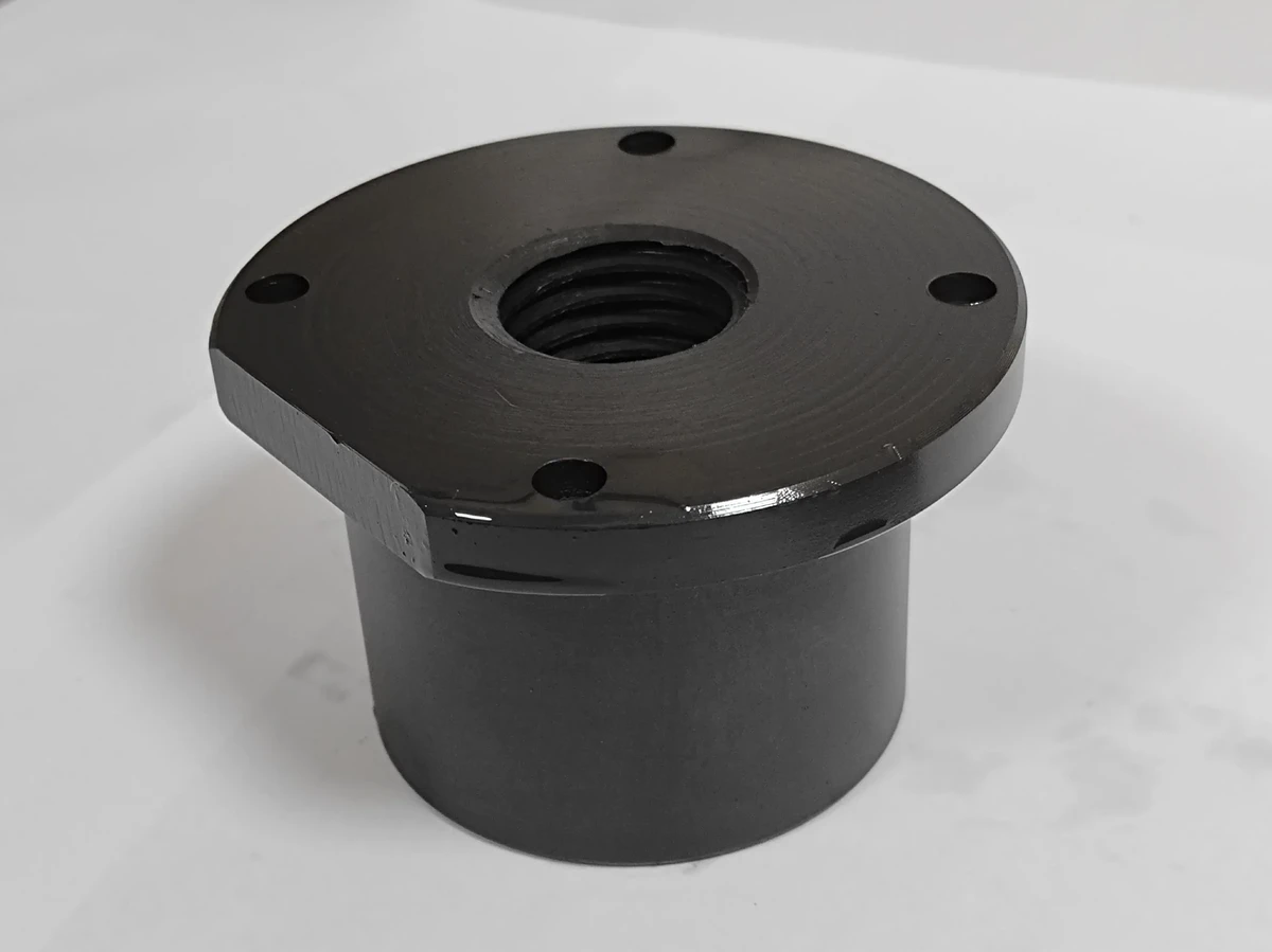
A crystalline conversion coating for steel that improves lubricant or paint adhesion and supports wear-in and corrosion protection.

Typical Applications: Aerospace fasteners and wear components

Dark phosphate-finished cylindrical component with an internally threaded flange
Laser EngravingDeep or surface marking

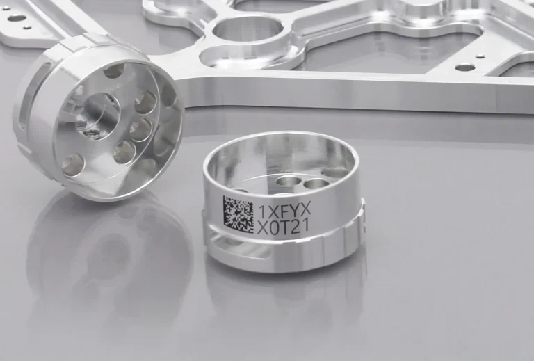
A permanent marking process for part numbers, lot codes and traceability without adding a separate label.

Typical Applications: Traceability and part numbers

Machined metal ring with a two-dimensional code and alphanumeric laser marks on its outer surface
Zinc PlatingDrawing-specified thickness and chromate

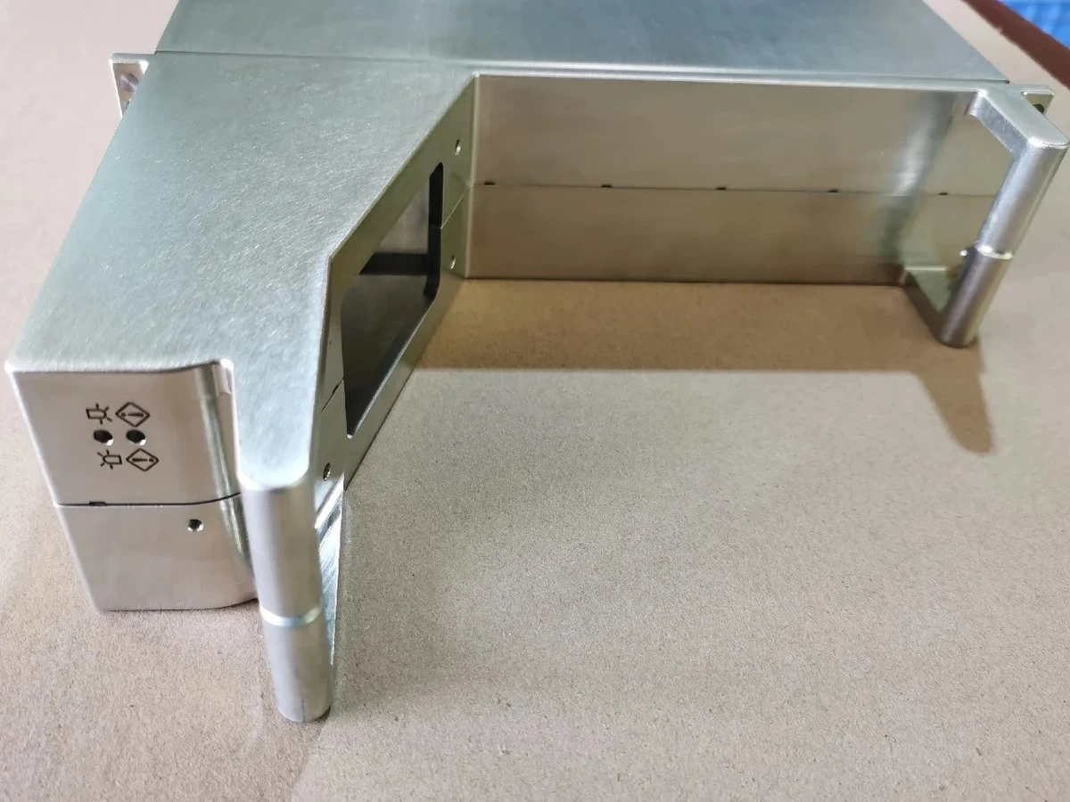
An electroplated zinc layer provides sacrificial corrosion protection for carbon and alloy steel components with controlled coating thickness.

Typical Applications: Steel fasteners, fittings and industrial components

Zinc-finished metal enclosure with machined openings and corner posts
Heat TreatmentHardness per drawing

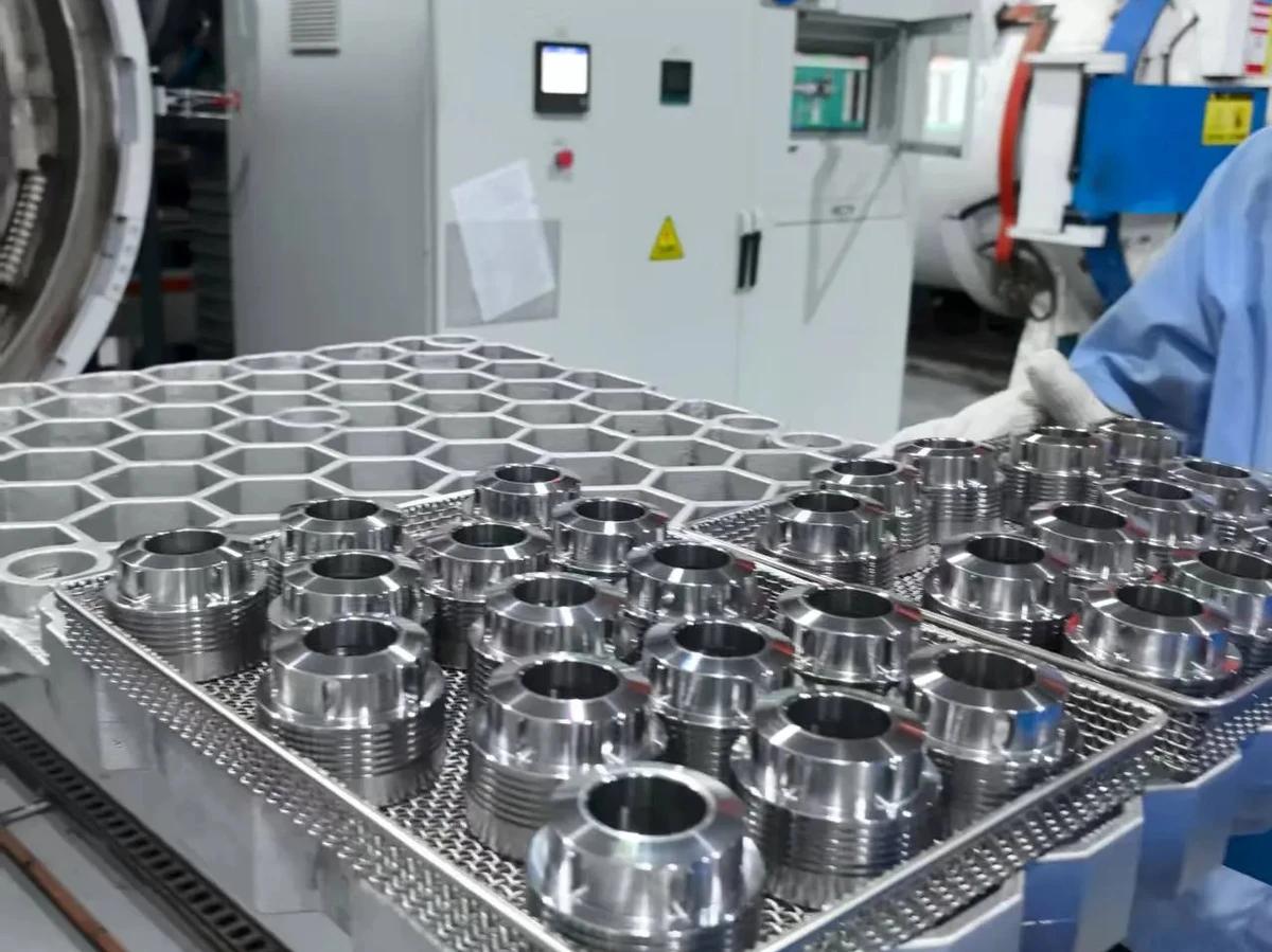
Through-hardening, case hardening or precipitation hardening is coordinated with material grade, distortion allowance and final dimensional verification.

Typical Applications: Shafts, pins, wear surfaces and load-bearing components

Metal components on processing trays beside heat-treatment equipment
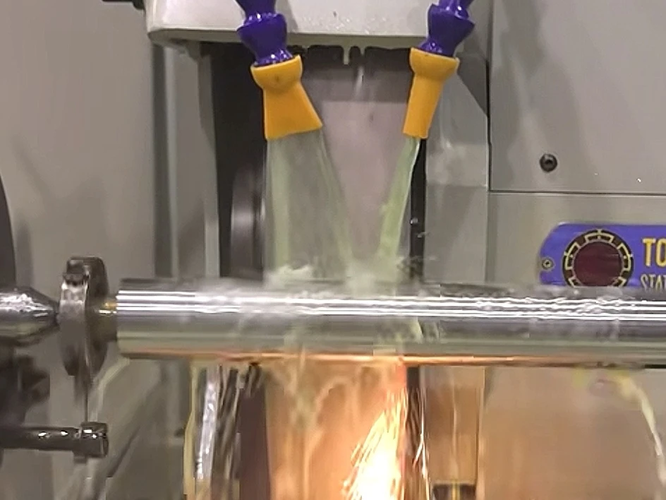
Cylindrical GrindingFine diameter and finish requirements

Grinding refines critical outside diameters, roundness and surface finish when a bearing fit or drawing requirement exceeds the practical turning limit.

Typical Applications: Bearing journals, locating diameters and sealing surfaces

A cylindrical metal shaft being ground with coolant at the grinding wheel

How We Check The Quality Of Your Components

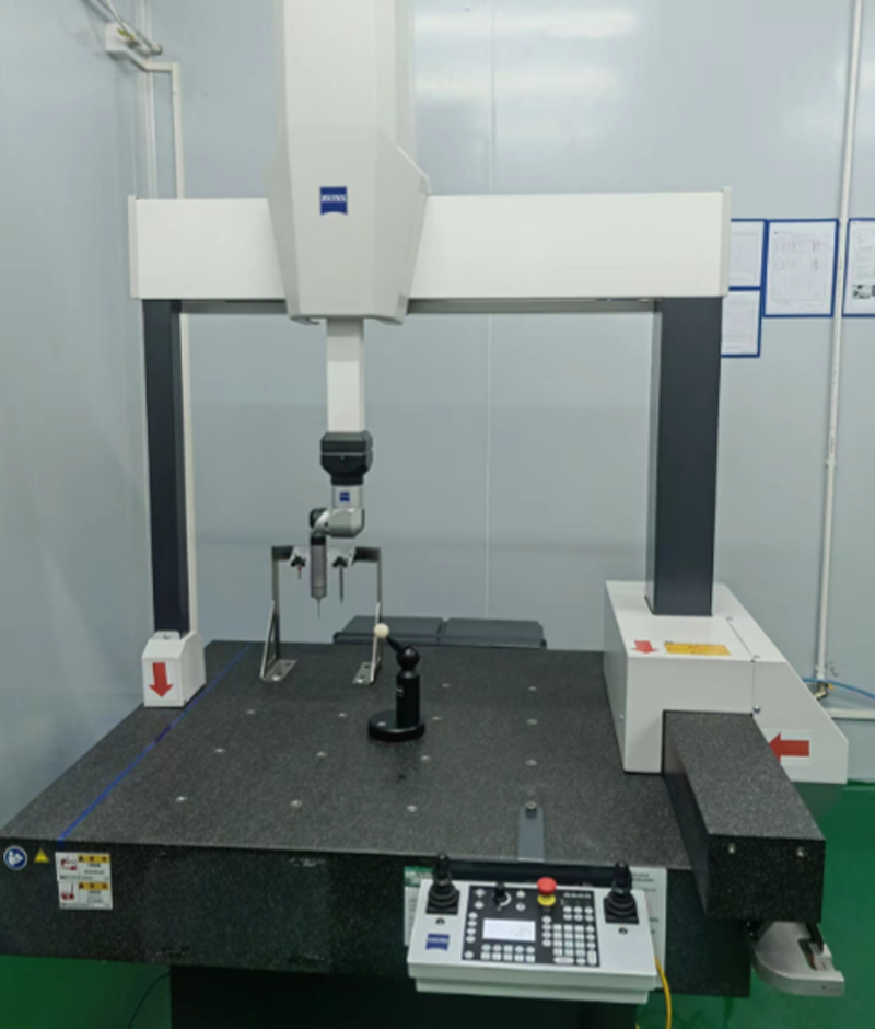
Every new turning setup begins with first-part verification against the released drawing. Critical diameters, threads, runout and surface finish are checked at defined intervals so predictable tool wear can be corrected before it creates a nonconforming batch. Final verification uses calibrated micrometers, gauges, vision systems, contour and roughness measurement, and Zeiss CMM programs where geometric relationships require them. Requested AS9102 FAI, material certificates, SPC evidence and certificates of conformance are defined at the RFQ stage. Additional checks use 10 microscopes for burrs, edges and surface condition, plus roughness instruments for drawing-defined surface finish.

ZEISS bridge-type coordinate measuring machine with granite table and control console in the factory measurement room

ZEISS CMM

Range
700 × 700 × 600 mm
Quantity
1
Use
3D dimensions, hole positions and geometric relationships.
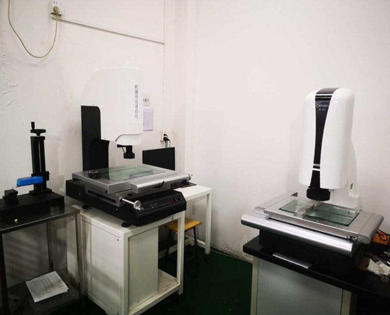
Two optical video measuring machines with glass stages in the factory measurement room

Vision Measuring Systems

Range
200 × 300 mm; 300 × 400 mm
Quantity
2
Use
Non-contact checks of profiles, edges and small features.
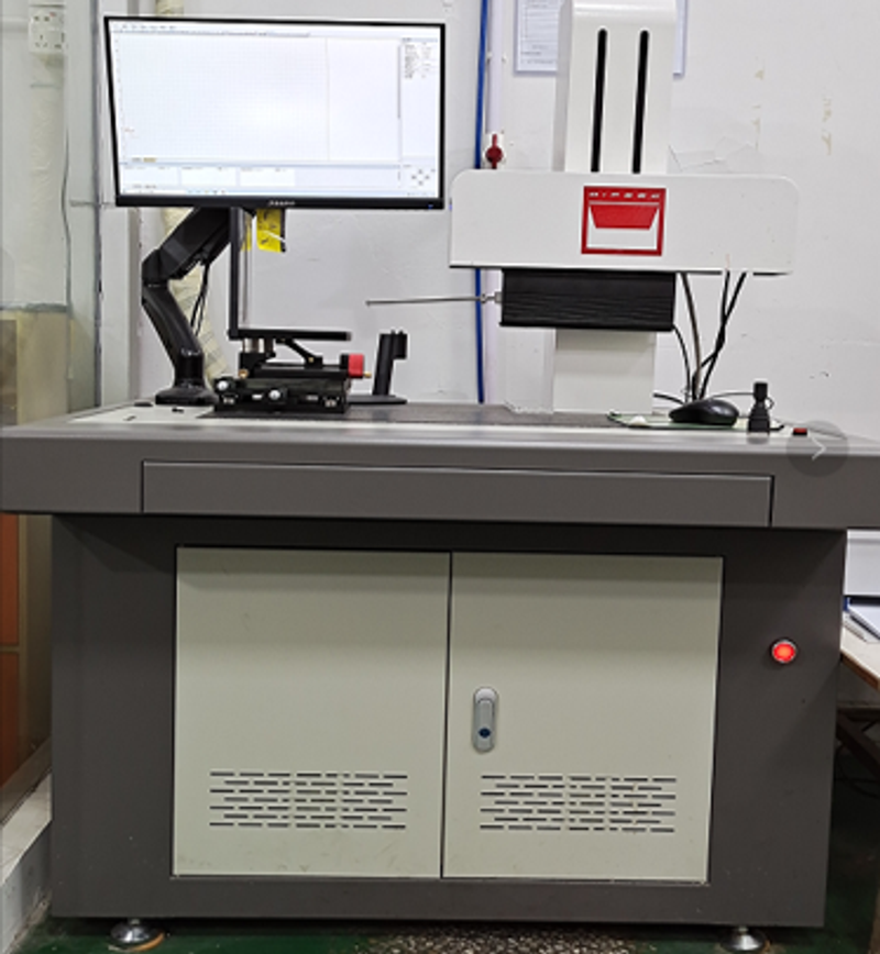
Factory contour measuring instrument with measuring arm, vertical column and computer monitor

Contour Measuring Instrument

Quantity
1
Use
Functional contours and profile geometry.
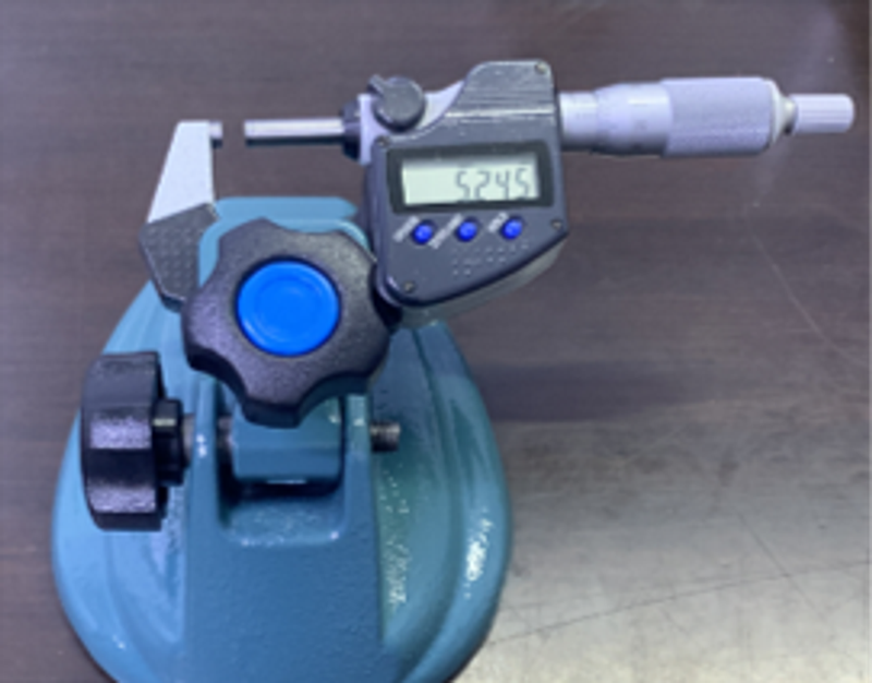
Digital outside micrometer held in a blue bench stand

Micrometers

Range
Outside: selected ranges 0–150 mm; inside: 12–88 mm and 50–600 mm
Use
Outside, inside and feature-specific dimensional checks.
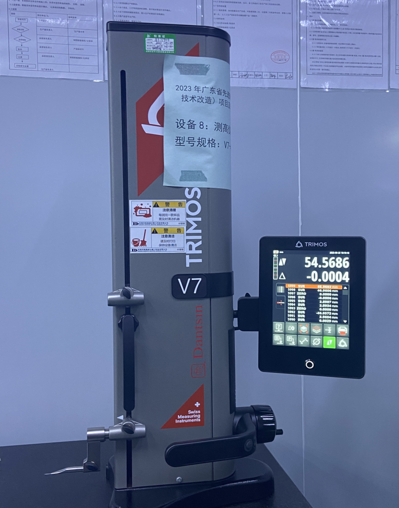
TRIMOS V7 digital height gauge with measuring probe and touchscreen display

TRIMOS V7 Height Gauge

Range
0–400 mm
Quantity
1
Use
Height and comparative dimensions from a reference surface.

Why Choose Our CNC Turning Services?

Our turning service connects engineering review, machine selection, workholding, live-tool planning, in-process control, qualified finishing and final inspection. One engineering team follows the drawing from quotation through repeat delivery.

  • Datum-Led Process Planning

    Related diameters, bores and faces are organized around functional datums to protect concentricity, runout and assembly fits.

  • MAZAK And TSUGAMI Capacity

    Multiple turning platforms let us select the route around diameter, length, feature mix, material and production quantity.

  • Live-Tool Options

    Cross-holes, flats and simple milled features can stay within the turning route when machine capability and geometry permit.

  • DFM With Every RFQ

    We identify tolerance, thread, wall-thickness and tool-access details that affect cost, stability and measurement.

  • Inspection Planned Upfront

    Critical diameters, threads, runout and surface finish receive a defined measurement method before production.

  • Prototype To Repeat Production

    Approved programs, setup records, inspection plans and revision controls support first builds, repeat batches and documented engineering changes.

Industries We Serve

CNC turning supports rotational components whose diameters, threads, sealing surfaces, runout and assembly fits must remain consistent from first article through repeat production and documented engineering changes.

Space launch vehicle tank and boosters against a blue sky

Aerospace

Concentric diameters, thread geometry and material traceability are planned around AS9100D-controlled production and drawing-defined inspection records.

Ti-6Al-4V · Inconel 718 · 15-5PH

Front view of a military aircraft on outdoor display

Defense

Process planning connects material identity, dimensional control and required documentation to the released drawing and contract requirements.

17-4PH · 4140 · 7075-T6

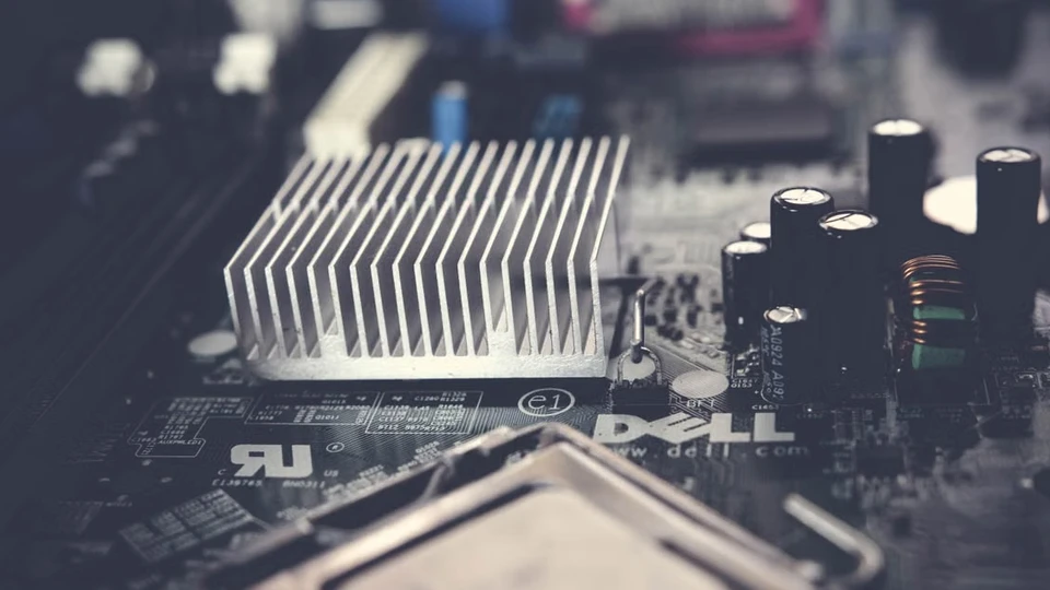
Electronic circuit board with a heat sink and semiconductor components

Semiconductor

Sealing diameters, internal bores and surface finish are reviewed with cleanliness and material records before production begins.

316L · C110 · 6061-T6

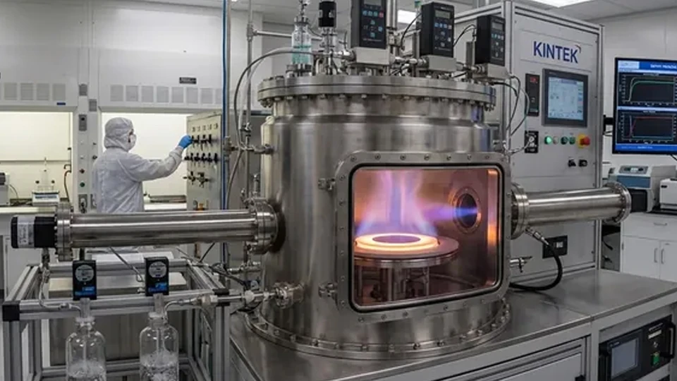
Vacuum process chamber with viewing window, pipework and control equipment

Vacuum Systems

Turning routes are built around sealing geometry, runout, surface finish and any specified leak-test or cleaning requirement.

316L · aluminum · PEEK

Autonomous wheeled delivery robots beside a building

Robotics

Bearing fits, thread relationships and concentric features are controlled from the functional datums that influence assembly performance.

Alloy steel · stainless steel · aluminum

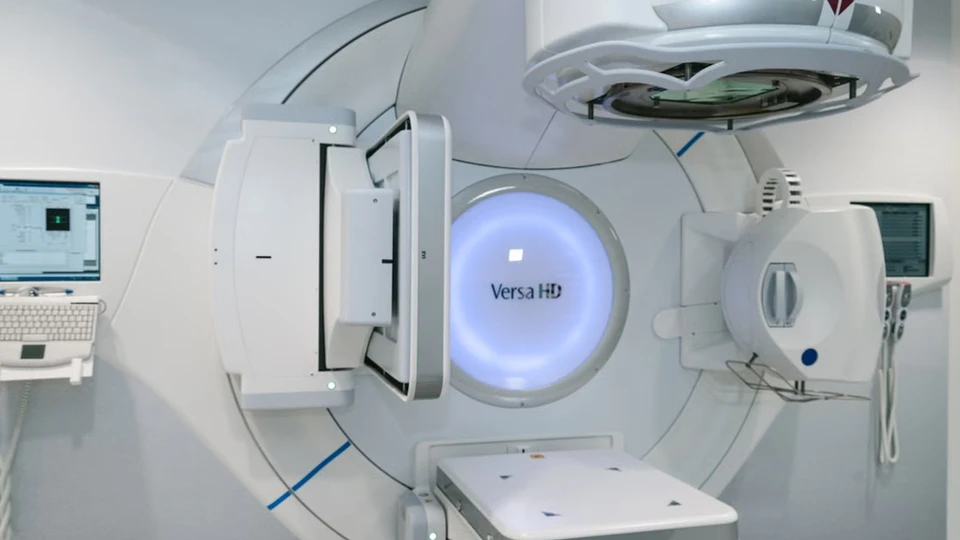
Medical radiotherapy equipment with treatment gantry and patient table

Medical

Customer-defined medical quality controls supports material traceability, edge requirements and drawing-defined inspection documentation.

316L · Ti-6Al-4V ELI · PEEK

What Is CNC Turning?

CNC turning shapes a component by rotating bar stock or a prepared blank against programmed cutting tools. The process naturally creates outside diameters, bores, faces, shoulders, tapers, grooves and threads around a common centerline.

Because related diameters and faces can be cut from the same rotational reference, turning is efficient at controlling concentricity, runout and assembly fits. A programmed turret changes tools quickly and repeats the same sequence from the first approved part through later production batches.

Live or driven tooling can add cross-holes, flats, slots and selected off-center features without transferring the work to a separate milling setup. When the milled geometry becomes substantial or requires tighter relationships across multiple faces, the drawing is reviewed for a mill-turn route instead.

Turning is usually the most economical process when the primary geometry is rotational. Prismatic blocks, plates and deep-pocketed housings are generally better suited to CNC milling, while small slender bar-fed components may be better matched to Swiss machining after engineering review.

A lathe cutting tool turning stepped diameters on a hollow metal component held in a chuck

Frequently Asked Questions

Clear answers about process selection, capability, documentation and quoting.

What Parts Are Best Suited To CNC Turning?

Parts whose primary geometry is rotational are the strongest candidates: diameters, bores, shoulders, grooves, tapers and threads organized around a centerline. Limited flats, cross-holes and slots can remain in the turning route when live tooling and geometry permit.

How Do CNC Turning And CNC Milling Differ?

Turning rotates the workpiece against cutting tools and is efficient for cylindrical geometry. Milling rotates the tool against a fixed workpiece and is better for prismatic geometry. Parts with substantial turned and milled features are reviewed for mill-turn machining.

Can Milled Features Be Added To A Turned Part?

Yes. Selected machines can add cross-holes, flats, slots and off-center drilling in the turning setup. The quote will identify whether live-tool turning or a mill-turn route offers the better balance of access, accuracy and cost.

What Tolerances Can You Hold?

The confirmed general values are listed in the capacity table. Final capability depends on material, geometry, unsupported length, wall thickness, feature relationships and inspection access, and is approved against the complete drawing.

Can You Support Prototype And Repeat Production?

Yes. The process route is planned for the requested quantity, and approved programs, setup records and inspection plans support continuity when the order moves from first builds into repeat batches.

What Quality Documents Are Available?

Drawing-defined inspection reports, material certificates, lot traceability, AS9102 first-article records, SPC evidence and certificates of conformance can be planned when requested at the RFQ stage.